- The ammonium perchlorate composite pre-heater grain is lit by electrical means
- Fuel in the core is heated past its ignition temperature at the surface by the hot gas flow produced by the pre-heater.
- The thermoplastic tubing used to prevent nitrous flow through the injector is melted by the burning pre-heater.
- Once the thermoplastic tubing is melted through, nitrous oxide flows through the injector and into the combustion port.
- Fuel in the port is combusted with the injected flow of nitrous oxide, sustaining hybrid rocket motor operation.
- Operation is automatically terminated when the nitrous oxide supply is depleted. The total amount of nitrous oxide allowed to flow into the motor is slightly less than the projected combustion O/F ratio times the total mass of fuel in the motor. This is a precaution that prevents the fuel and liner from being completely consumed, subsequently causing the motor casing to fail due to exposure to combustion gases.

Two pressures are collected over time. The first is the nitrous line pressure before entering the injector and the other being the pressure inside the motor. This differential pressure across the injector orifice is proportional to the square of the oxidizer flow rate. Also as the Mathematical Construct of Data Acquisition would suggest, knowing the instantaneous internal motor pressure of the motor, along with information about the nozzle throat area, total propellant consumed, and the propellant combination's characteristic velocity (a function of adiabatic flame temperature and product molar mass), allows for the determination of instantaneous regression information. Characteristic velocity data will be determined experimentally and theoretically using NASA's CEA code.
Two Taber 0-2000 psi pressure transducers are used in order to measure these pressures in terms of an amplified output voltage. A basic instrumentation amplifier can be seen in my last post. These transducers utilize a resistor bridge that deforms under pressure, varying the electric potential across the output leads given a constant input potential. Moreover, the connection of a resistor across an input terminal to its corresponding output terminal can simulate a measured pressure in terms of output voltage. In the documentation for the transducers, several data points are given as resistances and corresponding simulated pressures. Using a power regression, one determines the relationship:
P=5558.781 * R^(-.99808393)
 |
| Transducer Resistor Bridge Schematic |
For an arbitrary constant input voltage between 10 and 15 volts. A voltage regulator has been constructed to supply a constant 12 volts to each transducer. Several pressures will be simulated and the amplified output voltages at constant gain recorded. These data will provide a calibration curve for the sensors that can be used as long as the input is 12 volts and the gain is constant.
In other words: Resistance ==> Pressure <==> Voltage
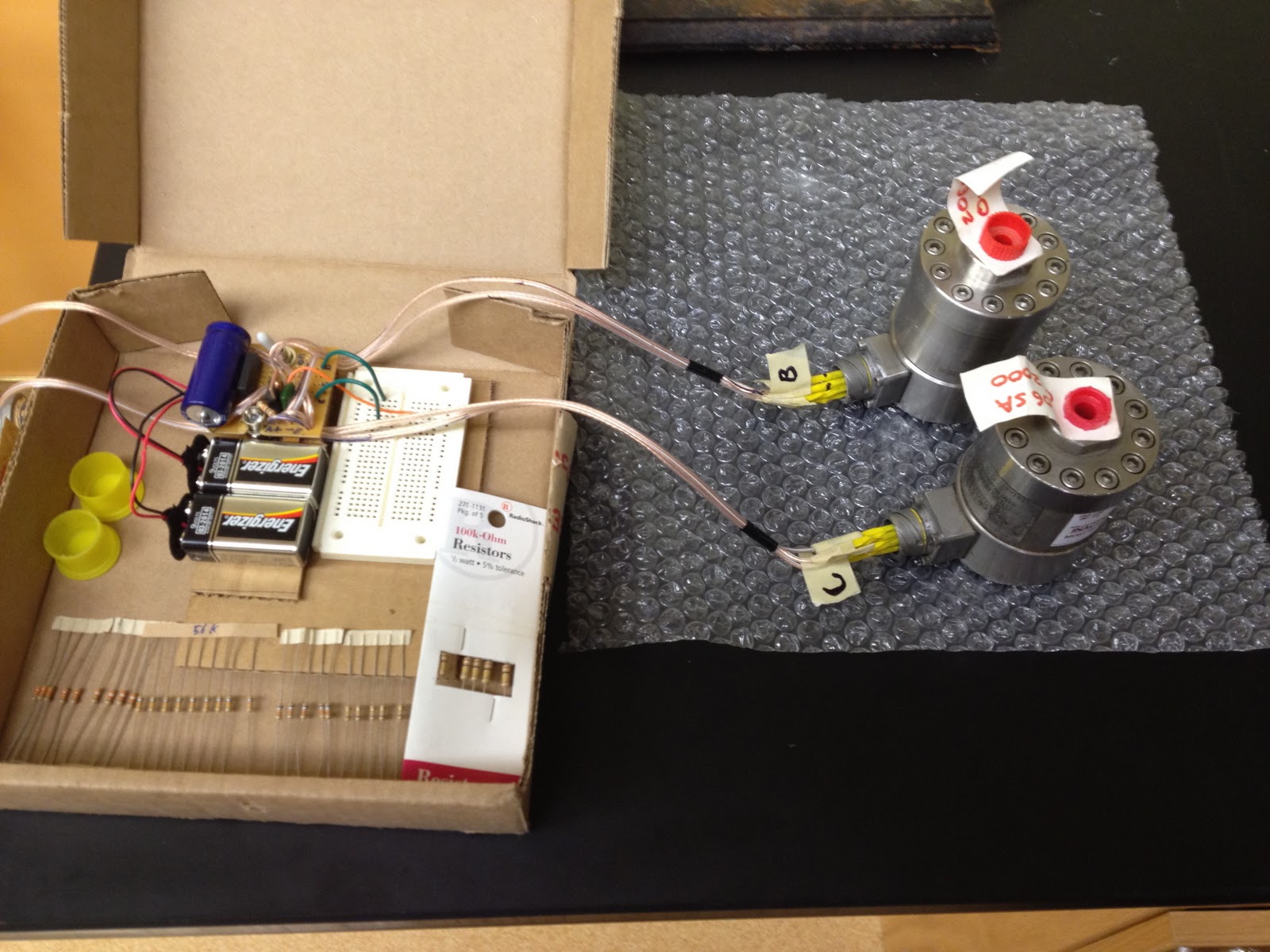 |
| Voltage Regulator Connected to the Transducers |
 | |
| Voltage Regulator With Calibration Resistors |
I have begun work on the oxidizer feed system. On Tuesday, I went out to a local automotive shop specializing in racing and acquired a 20lb cylinder of nitrous oxide. This should be enough to run all of my trials on a single fill. All of the parts for the remainder of the oxidizer feed system have been ordered from McMaster Carr and should arrive early next week. I decided to use a 72 cubic inch high pressure cylinder that I had (for paintball) to store the nitrous oxide in individual trials. With 200 g of propellant and an O/F of ~3.5, over 90 cubic inches of liquid nitrous would be needed. Therefore, the 72 cubic inch tank should work perfectly. The tank was drained and the valve assembly removed and disassembled. Removing the regulator, I turned the remaining threaded part that connects to the tank itself on the lathe. A wider port was bored and will be taped for 1/4" NPT threads to accommodate higher flow rates. Also, a hole will be drilled and taped for 1/8" NPT threads at the opposite end of the cylinder. A ball valve and .029" orifice plug will be installed here. This assembly will vent the excess air and nitrous oxide as the liquid nitrous fills the tank. Once filling has ended, the valve is closed, preventing further venting.
 |
| Oxidizer Feed Schematic |
Thanks For sharing such a Good information about aerospace Engineering.
ReplyDeleteIn this day of the information age it has never been easier to find out what you need to know in order to hire the right design engineer for the job. No matter if your job is a small one of a large one you still need to make sure that the design engineer that you choose is reliable and trustworthy and that they actually know what they are doing.
ReplyDeleteaerospace engineering jobs
The ammonium ionic liquid is a compound in which hydrogen atoms in the ammonium ion are substituted by alkyl groups, and its general formula is R4NX, and the four alkyl groups may be the same or different groups. Ammonium ionic liquids
ReplyDeleteThis is highly informatics, crisp and clear. I think that everything has been described in systematic manner so that reader could get maximum information and learn many things.
ReplyDeleteclick here